Kirwan, Forces Exerted Between Parallel Conductors, TPT 13, 113-114, (1975). K1-01: FORCE BETWEEN CURRENT-CARRYING WIRES Bruce Bernero, A Demonstration of Magnetic Force Upon a Current-Carrying Wire, TPT 25, 88, (1987). Note that the applet will take a few minutes to load.REFERENCES REFERENCES SECTION K K1: FORCES ON MOVING CHARGES You should observe that the particle travels undeflected through the apparatus if your velocity calculation is correct. Show your work and use the Thomson’s Charge/Mass Measurement simulation to verify your answer by setting the calculated velocity, magnetic field, and electric field as stated. Use Equation 1 to determine how fast it is travelling. A particle travels undeflected (straight) through a Thomson apparatus that has a magnetic field of 2.0 T and an electric field of 100 V/m oriented perpendicularly to one another.

The electric field is oriented downward and the magnetic field is into the page. A beam of electrons is fired to the right into a set of perpendicular electric and magnetic fields. When the particle travels straight through, Equation 1 can be used to calculate its speed.

This way, if the magnetic force were equal in magnitude to the electric force, the particle would travel straight through the apparatus. He set up the apparatus in such a way that the electric force was oriented opposite to the magnetic force. Thomson used this knowledge to determine the speed of a travelling particle using both a magnetic and electric field simultaneously. Part 1: Determining the Speed of a Cathode Ray ParticleĪ magnetic field or an electric field acting alone will deflect a charged particle that is travelling perpendicularly to it. First, he used his apparatus to determine the speed of a cathode ray particle in the tube then, knowing the speed, he used the apparatus to determine the charge-to-mass ratio of the particle. Using only these two forces, Thomson designed an experiment that consisted of two basic investigations. Recall: In the open palm left-hand rule for negative charges, the thumb goes in the direction of movement ( ), the fingertips go in the direction of the magnetic field (out of the page in this case), and the palm points in the direction of the force on the charge. Recall the equations and hand rules that describe these forces. The design of his experiment is based on electric and magnetic forces that act on charged particles. In other words, he designed an experiment to determine the amount of charge per unit of mass for the particles in the cathode ray. He was unable to measure either the charge or mass by itself, but he was able to measure them both as a ratio. Thomson attempted to measure both the mass and charge of the negative particles making up the cathode ray. What was the evidence that the cathode rays were particles with charge and mass? Remember to submit your answer to A 1 to your teacher as part of your Module 7: Lesson 1 Assignment.Ī 1.

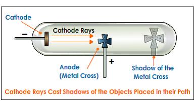
Read “Cathode-ray Experiments” on pages 754 to 755 of your physics textbook. are deflected by magnetic and electric fields and have a negative charge.travel in straight lines and cause shadows.travel from the negative electrode to the positive electrode.The direction of deflection of the cathode rays further proved that they were, in fact, negative.īased on these observations, cathode rays Using the left-hand rule for moving electric charges in a magnetic field, he proved that the particles were negatively charged and were emitted by the cathode.Īrthur Schuster used a set of external charged plates to demonstrate that the cathode rays were affected by electric fields. This proved that cathode rays were composed of moving particles that had mass and momentum and were capable of doing work.Ĭrookes also demonstrated that cathode rays are deflected by a magnetic field. When the rays hit the paddles, they caused the wheel to move along a track inside the tube.
CATHODE RAY EXPERIMENT DIAGRAM FREE
Crookes placed a paddle wheel, which was free to rotate, in the path of the cathode rays. For this reason, gas discharge tubes are sometimes called Crookes tubes or, more commonly, cathode ray tubes (CRT). William Crookes proved that the emissions travelled from the cathode to the anode.

Immediately, the cathode ray became the subject of intense experimentation. This diagram is an illustration of a simple gas discharge tube. Cathode ray: a free electron emitted by a negative electrode in a low-pressure environment


 0 kommentar(er)
